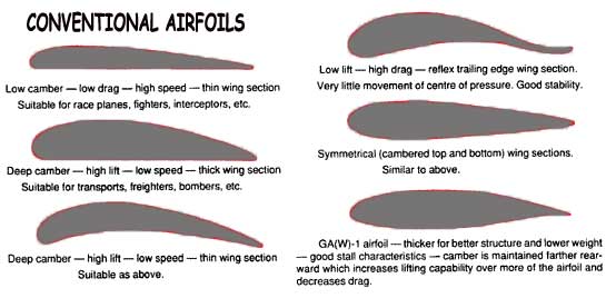
Fixed wing drones can come in a variety of configurations.

The layout of a rotary drone enables hovering, but fixed wing drones are significantly more efficient, enabling longer flight times. Whereas, fixed wing drones use conventional wings to generate lift as they travel through the air. The former, such as quadcopters, rely on propellers to generate vertical thrust and hold themselves aloft.

There are two common styles of drone design: 1) Rotary drones 2) Fixed wing drones. When comparing wing designs, make sure your performance priorities align with the intended application. It is important to use the appropriate value for your application beforehand to ensure you are properly evaluating a potential design.Īirfoil selection generally involves compromise between optimal performance, efficiency and a consistent range of operation. The performance of an airfoil also changes with different Reynolds number. These generalized coefficients allow you to compare different airfoils for any given cross-sectional area. This will be demonstrated with an example using a typical airfoil profile known as the NACA0012.Ĭomparison plots between the NACA0012 (blue) vs NACA6412 (orange) Design considerationsĪirfoil performance is usually characterized by the calculation of drag and lift coefficients, instead of the absolute force produced. The lift and drag forces generated by an airfoil vary as the angle of attack changes. What are the different sources of aerodynamic drag? This is why the upper and lower surfaces are also referred to as the suction and pressure surfaces, respectively. The resulting pressure difference between the two surfaces is what generates a lift force. Air travelling over the upper surface accelerates while air along the lower surface slows down.Īccording to Bernoulli’s principle, this creates an area of low pressure above the wing, and high pressure below the wing. Airfoils generate lift by displacing the airflow, inducing a net curvature as air is directed downwards. These are commonly used as metrics to compare wing performance. When normalized by the planform area and the dynamic pressure, the lift and drag coefficients, CL and CD, can be calculated. Lift is the force generated by an airfoil perpendicular to the wind, while drag force is measured along the wind direction. The relative wind direction can be calculated from the velocity vectors of both the wind and the object itself. The leading and trailing edges are connected by the upper surface and the lower surface of the airfoil.

Illustration of the different components of an airfoil


 0 kommentar(er)
